|
|
Joined:
November 2007
Posts: 125
Location: UK | Hi
Help please.
Finally got round to putting my Breadwinner bits back together. Down to the electrics now. Ok, so the "reds" are easy - nicely labelled on the pcb but .... there are an awful lot of black/earth wires! I have the two from the pups, plus a couple to earth the pup cases and then there is the earth from the mount plates. There seem to be two areas on the pcb that these could go.
Thanks
Paul |
|
| |
|

Joined:
December 2003
Posts: 13996
Location: Upper Left USA | Piece of cake man!
 |
|
| |
|

Joined:
December 2003
Posts: 13996
Location: Upper Left USA | Paul,
I have some pics at home I'll have to go through and send you. Jerome has a wire color chartat his site that might help as well. |
|
| |
|
Joined:
November 2007
Posts: 125
Location: UK | Thanks Mike
I await, but if they are anything like the one above well..........
Perhaps not.
Tried the schematic but, well they are schematics and I don't speak that language.
Paul |
|
| |
|
Joined:
March 2005
Posts: 2791
Location: Atlanta, GA. | Woody,
Local Telco installation?
Definetely not WECO!!! |
|
| |
|
Joined:
August 2006
Posts: 3145
Location: Marlton, NJ | I don't know Colin... I've seen old WECO central offices that looked pretty much exactly like that. |
|
| |
|
Joined:
June 2007
Posts: 270
Location: Yorkshire, England | Paul, try this - I'll explain as best I can -
If you have the back of the cct board facing you, you should have the battery connection wires fixed to the bottom left hand side.
You should see a solder point almost bang in the middle, right on the bottom edge - this is where the bridge/tailpiece earth wire goes.
The last soldering point on this line is also an earth point from the pickups.
Hope this is some help, wish I take a look at it for you to see what's going on -
If you need any more help, get in touch - let us know how you progress.
Any of your earth wires you have spare (if you know they're earths) should, in theory, be able to be fixed to this solder point. |
|
| |
|
Joined:
November 2007
Posts: 125
Location: UK | Thanks Clyde
Had a quick look and that seems to be what I expected. There is also what looks like another solder point just to the right of this.
Looks good. Maybe I will try and take some pictures to be on the safe side.
Post in the US, get a reply from God's county.
My regards to Yorkshire
Paul |
|
| |
|
Joined:
June 2007
Posts: 270
Location: Yorkshire, England | Paul - Here's something a bit more exact -
(Always good to have it written down, never know when you might need it !)
Shielded/Bare Metal Wire (From Bridge p/up)
- Goes to the solder point furthest right on bottom edge of cct board.
The x2 Black Wires from the Bridge p/up go to the solder point just next to it on the left.
(They are very close together)
The Black wire from the neck p/up, again goes to the first solder point I mentioned - furthest right on bottom edge.
If you have any wires left over !?! let me know and we'll see if we can sort it.
Best of Luck ! |
|
| |
|
Joined:
June 2007
Posts: 270
Location: Yorkshire, England | Paul, just in addition, you'll have a bare metal wire running from the bridge p/up to the neck p/up. If you're ok with the reds, this should tie everything up. |
|
| |
|
Joined:
January 2006
Posts: 1130
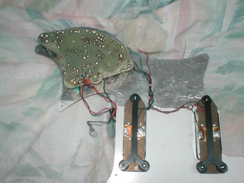
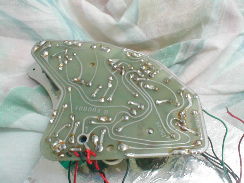
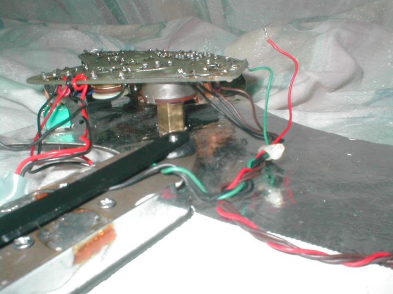
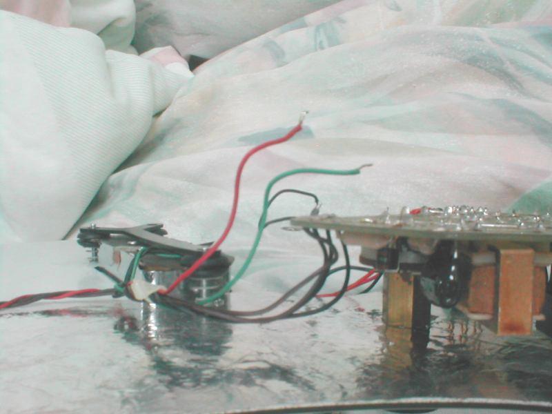
Location: NW Washington State | Here's a Breadwinner pickguard assembly. This one has brown ground wires on the neck pickup and black ones on the bridge pickup. All four wires go to the ground trace on one corner of the board. There's a separate through-hole for each. The bridge grounding wire is attached a little further down the trace. The "hot" wires are green and red. I must have detached them during one of my science projects.
Your Breadwinner may vary...
 |
|
| |
|

Joined:
December 2003
Posts: 13996
Location: Upper Left USA | Here's Mo...
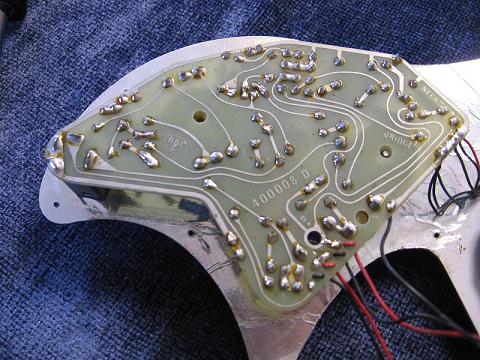
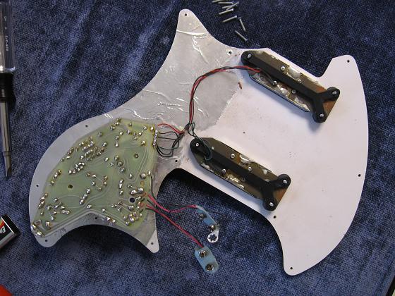
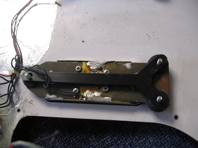
Sorry to take so long. Yesterday was the Deck extension and BBQ and this morning was the Flu and and projectile heaving. going back to bed... |
|
| |
|

Joined:
June 2007
Posts: 3084
Location: Brisbane Australia | Hey, that looks suspiciously like the pile of bits and pieces I recieved from the US this morning :D
AJ |
|
| |
|
Joined:
June 2007
Posts: 270
Location: Yorkshire, England | Hi, Paul - I get the impression that you have the earlier type pick-ups, if you're still struggling after all of the above, if you want to send me your address, I'll draw you a (straight forward) circuit diagram. |
|
| |
|
Joined:
November 2007
Posts: 125
Location: UK | Great pictures - Thanks Mike.
And yes, Clyde, I do have the early original pickups. These have three wires, one red, two black - I suspect that the second black is the earth for the casing. Also the plates that that support them have bare earth wire. I will get some pictures asap, before I "plug in". Despite all the help I am still feeling a but .. "doh".
I have a glorious refurbished white Breadwinner with a fine pair of passive Gibsons. I have all the original parts and am aiming to switch the scratchplates and give the old system a try. But who knows, I may well revert to the Gibsons in the end.
Thanks again for all the help.
Paul |
|
| |
|
Joined:
June 2007
Posts: 270
Location: Yorkshire, England | I'm quite envyous Paul - I had a black Breadwinner that I Ebay'd for a fraction of the price I bought it for, now I'm (kind of) on the outlook for another as I miss it quite a lot. (Always hankered after a white one really!) I ummmmed and ahhhhhhed over a couple that came up on Ebay as they seemed a bit pricey (£750 & £539 + postage) but wonder if I should have gone for them. The electrics on the one I had went kaput quite soon after I got it, and I ended up putting Gibson PAF's on.
Can't begin to tell you what a fantastic guitar I think they are.
Best of luck with it anyway Paul, keep us informed ! |
|
| |
|
Joined:
June 2004
Posts: 9
Location: Houston, TX | Can someone please email me a wiring diagram for this also? I have a white 1972 Breadwinner that had a loose capacitor. When taking the pickguard off (and neck), a back wire from the board came loose. I fixed the cap problem but do not know where this black wire solders to. It on the battery terminal side of the board - there are 3 black wire, 2 go to the terminal and I have no idea where this one goes. At the moment only the neck pickup works because of this issue. My guitar has the bigger pickups and differs than the board pictures here. HELP......I need somebody!
-Joe
joe.baiardi@jacobs.com |
|
| |
|
Joined:
June 2007
Posts: 270
Location: Yorkshire, England | Hi Joe - You'll have the single coil Torodial type p/ups - If you can say a little more exactly where it's running from, I can probably help with this. Is it one of the Black wires from the bridge p/up that you can't find a connection point for? |
|
| |
|
Joined:
June 2004
Posts: 9
Location: Houston, TX | Clyde.....it's this exact guitar and pickups.

It's a black wire that's coming off the the circuit board on the underside next to the 2 black wires that are paired up with reds to the battery connections. I'm not sure if it's solder to the bridge or somewhere else. |
|
| |
|
Joined:
December 2001
Posts: 7240
Location: The Great Pacific Northwest | You may have TWO issues.
If you have at least two leads coming from each pickup, to the circuit board, and probably a third ground lead also coming to the circuit board, than the "extra" you have from the circuit board probably goes to the bridge. There should be a lug washer on the bridge post. Just look in the battery compartment. If the lug washer is broken, you can replace it, or just solder the ground to a washer and use it.
However,...... This wire not being hooked up might make things noisey...and it would effect BOTH pickups as it's just a ground.
There is also a chance, and I'll assume you checked, that the stray black wire belongs to one of the 9Volt leads. Again, this would affect BOTH pickups.
If one pickup isn't working, you need to test that pickup.
Unsolder it from the circuit board and check the impedance across the red an black leads. Should be somewhere around 7.5K ohms, maybe a little higher.
If the pickup in question is good, then check the solder points of the selector switch. If the board wasn't mounted properly, slight misalignment, can pop a solder joint over time.
For anyone replacing a switch, I mount the switch to the pickguard, then set the circuit board into place, then solder. This was I know none of the tangs are being stressed. |
|
| |
|
Joined:
June 2007
Posts: 270
Location: Yorkshire, England | Joe - do you mean this wire is connected TO the cicuit board? Also is it positioned roughly in the middle of the cct board ? If so this is the Earth wire which connects to the bridge/tailpiece.
Don't know why this would give you bridge p/up failure though ! It would/should only cause hum. |
|
| |
|
Joined:
June 2004
Posts: 9
Location: Houston, TX | Miles:
I will check it out. This is good info. So there really is a black wire coming from the board to the bridge? I solder it to the jack ground so that may be causing all of this mess. I will solder it to the bridge ground and see what happens.
If you have a picture of that wiring diagram, can you please send it?
Cheers
Joe |
|
| |
|

Joined:
June 2007
Posts: 3084
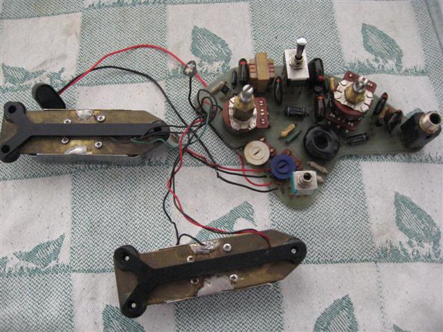
Location: Brisbane Australia | I've just resoldered this.
About to power it up see if there's any honk
 |
|
| |
|
Joined:
December 2001
Posts: 7240
Location: The Great Pacific Northwest | In the above picture from AussieJames you can see the little lug washer. It's hanging in this photo right near the upper left of the board, over the red 9v lead. That washer goes under the nut in the battery compartment that hold the bridge in.
Again, if you went to ground on the jack instead, it still shouldn't affect only one pickup, so I still am thinking you have two issues. One being the stray wire which being that it's black is a ground, the other is one pickup doesn't work. |
|
| |
|

Joined:
June 2007
Posts: 3084
Location: Brisbane Australia | Miles, do you have one of the switches next to the blue adjuster? You can see theres no toggle in it.
BTW I'm still working on the list.
AJ |
|
| |
|
Joined:
June 2007
Posts: 270
Location: Yorkshire, England | Joe - It shouldn't matter which ground you solder it to, an earth is an earth, as Miles says, I think it may be some other problem. Take a look at the bridge p/up wiring. |
|
| |
|
Joined:
June 2004
Posts: 9
Location: Houston, TX | Well........I have a black (spliced to green)wire going from the bridge PU to the bridge washer/lug. So the black wire coming from the board still has no where to go. Help Clyde and Miles.
http://www.thefab5.net/BREADPICT0025.JPG
http://www.thefab5.net/BREADPICT0027.JPG
http://www.thefab5.net/BREADPICT0028.JPG |
|
| |
|
Joined:
January 2006
Posts: 1130
Location: NW Washington State | I don't have those pickups or that preamp, and I'm not looking at mine right now. Just a couple of ideas and questions to throw into the discussion.
At first glance, I would expect the black/green spliced wire to connect to the ground trace on the preamp (the ground trace runs all around the edge of the PC board). But I don't understand why there would be two black wires, plus a grounding braid, coming from one pickup, where the other pickup has only one black wire. Is that the case?
Shouldn't the the output jack have some provision for switching the batteries? Maybe a stereo jack with the extra terminal used to connect the batteries when a mono plug is inserted? Or a jack with switches built in? Yours looks like an ordinary output jack. As Miles suggested earlier, maybe the extra black wire has something to do with the batteries.
-Steve W. |
|
| |
|
Joined:
June 2004
Posts: 9
Location: Houston, TX | What type of output jack is required on these guitars? |
|
| |
|
Joined:
December 2001
Posts: 7240
Location: The Great Pacific Northwest | I can't tell what's going on from those pictures, but this should be pretty simple. The board is labeled and we know some things...
- The Pre-amp may work. One pickup gives good sound.
- If the Vol and Tone work.. the board works.. at least mostly.
Insure the labels are followed...
- BRIDGE is the red lead from the bridge pickup.
- NECK is the red lead from the neck pickup
- OUT is the red lead to the output jack.
- Everything else is ground.
Things of Note.
- I can't tell from the picture, but it looks like one of the 9V leads is not connected to the right spot. I can't really tell from the photo, but I'll assume for now, if the Vol and Tone work, that it is correct and just looks funny.
- The Jack is wrong. It should be a switching Jack.
If you want me to fix it up for you, send me an email to Mileskb @ aol.com |
|
| |
|
Joined:
June 2004
Posts: 9
Location: Houston, TX | Here is the history of my problem(s). The guitar worked fine until last week. I took the pickguard off because a cap was loose. As I was taking off the guard the black wire became disconnected. I also thought there was a jack problem so I replaced it.
Now I want to get a new "Correct" jack for it and reconnect the black wire from wherever it got disconnected. So are there (3) wires that connect to the switching jack? Does anyone have a pic of their switching jack and wiring? |
|
| |
|
Joined:
December 2001
Posts: 7240
Location: The Great Pacific Northwest | I took the pickguard off because a cap was loose.
- Curious how that diagnosis was made..
As I was taking off the guard the black wire became disconnected.
- Probably the one that goes to the bridge.
I also thought there was a jack problem so I replaced it.
- It is supposed to be a switched Jack.
Now I want to get a new "Correct" jack for it and reconnect the black wire from wherever it got disconnected.
- Good Plan
So are there (3) wires that connect to the switching jack?
- Yes, actually may be four, but I'll have to go look at one. Been awhile since I worked on one that wasn't mounted to the circuit board.
Does anyone have a pic of their switching jack and wiring?
- I will go see. |
|
| |
|
Joined:
January 2003
Posts: 1498
Location: San Bernardino, California | 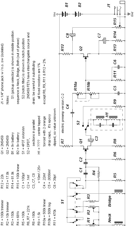
Early version large single coil preamp. |
|
| |
|

Joined:
June 2007
Posts: 3084
Location: Brisbane Australia | Thanks Bru very handy to have.
AJ |
|
| |
 Breadwinner wiring help.
 Breadwinner wiring help.